Synonyms: 
DC8
DC-8
NASA DC8
NASA DC-8 -AFRC
Associated content: 

Aerosol/Cloud Particle Impactor/Replicator

Aerosols of size 0.05 µm to 5 µm are collected with Ames wire impactors. This instrument consists of 25 µm, 75 µm and 500 µm diameter palladium or gold wires on ring mounts exposed to air for up to 5 minutes. Smaller diameter wires utilize their higher collection efficiency for small particles. Alternately, the wires can be replaced by Formvar-coated glass rods to collect cloud particles of sizes up to 500 µm. The collectors are brought back to the laboratory for analysis of size, shape and elemental/chemical composition of the collected particles using optical and electron microscopy, energy-dispersive X-ray spectrometry and microchemical reaction spots on substrates sensitized with specific chemicals.

Improved time and space resolution of ice particle collections is achieved by simultaneous sampling with the continuous Formvar replicator. The prime utility of this instrument is to obtain direct measurements of ice and liquid (volatile) particle concentration, size (1µm < D < 500µm) and shape over the period of approximately 2 hours per flight with a spatial resolution on the order of 20 m (at aircraft speed of 200 m/s). This opens the possibility of obtaining horizontal and vertical gradients of these quantities in cirrus clouds and contrails. Analysis of particles replicated on the films takes place by optical microscopy, interference microscopy and electron microscopy. The phases of supercooled or supersaturated solution droplets can be inferred from whether or not particles shatter or splash on impact to give sharp edged fragments or splash characteristics of high impact speed and high Langmuir numbers (high kinetic-to-surface surface energy ratios).

Measurements: 
Aircraft: 
Point(s) of Contact: 

Multicenter Airborne Coherent Atmospheric Wind Sensor

MACAWS is an airborne side-scanning Doppler laser radar (lidar) which measures two dimensional wind fields, vertical wind profiles, and aerosol backscatter from clear air and clouds. Range varies from 10-30 km depending on aerosol abundance and cloud attenuation. Upon exiting the aircraft, the lidar beam is completely eye-safe. MACAWS is developed and operated cooperatively by the atmospheric lidar remote sensing groups of NASA Marshall Space Flight Center, NOAA Environmental Technology Laboratory, and Jet Propulsion Laboratory.

MACAWS consists of: a frequency-stable pulsed transverse-excited atmospheric pressure carbon dioxide laser emitting 0.5-1.0 J per pulse at 10.6 micron wavelength at a nominal pulse repetition frequency (PRF) of ~20 Hz; a coherent receiver employing a cryogenically-cooled HgCdTe detector; a 0.3 m off-axis paraboloidal telescope shared by the transmitter and receiver in a monostatic configuration; a ruggedized optical table and three-point support structure; a scanner using two counter-rotating germanium wedges to refract the transmitted beam in the desired direction; an inertial navigation system (INS) for frequent measurements of aircraft attitude and speed; data processing, display, and storage devices; and an Operations Control System (OCS) to coordinate all system functions.

Instrument Type: 
Aircraft: 
Point(s) of Contact: 

Airborne Rain Mapping Radar

The NASA/JPL Airborne Rain MApping Radar (ARMAR) was developed for the purpose of supporting future spaceborne rain radar systems, including the TRMM PR. ARMAR flies on the NASA DC-8 aircraft and operates at 13.8 GHz (Ku-band); it has Doppler and multi-polarization capabilities. It normally scans its antenna across track +/- 20 degrees but can also operate with its antenna pointing at a fixed angle. In addition to acquisition of radar parameters, it also spends a small fraction of its time operating as a radiometer, providing the 13.8 GHz brightness temperature. ARMAR is a pulse compression radar, meaning that it transmits an FM chirp signal of relatively long duration. The raw data is recorded directly to a high speed tape recorder. Post-processing occurs in two steps; first, the raw data is compressed by correlating it with the transmitted chirp, giving data comparable to a conventional short pulse radar. These data are used to form various second-order statistics, which are averaged over at least 100 (often several hundred) pulses. The second processing step takes the pulse-compressed and averaged data and performs calibration. This step uses data acquired by the system calibration loop during flight to convert the measured power to the equivalent radar reflectivity factor Ze. It also produces Doppler velocity and polarization observables, depending on the mode of operation during data collection.

Instrument Type: 
Aircraft: 
Point(s) of Contact: 

Continuous Flow Diffusion Chambers

The continuous flow diffusion chambers are oriented for vertical flow through an annular space. They are constructed of two cylindrical, thin, ebonized copper walls that are separated by approximately 1.1 cm. The walls of the CFDC are force-cooled either by circulating coolant through copper tubing coils surrounding the outer wall and inside the inner wall (laboratory CFDC) or by using these same coolant coils as evaporators for refrigeration compressor units (aircraft CFDC). In operation, the walls are coated with ice, achieved by flooding the chamber with water. An inlet manifold directs sample air containing aerosol particles into the center of a laminar flow field where the sample is surrounded on either side by particle-free sheath air (or N2). By varying the set temperatures of the two walls, the warm wall provides a vapor source to the cold wall so that water vapor and temperature fields are created. These fields and airflow determine the conditions of exposure for the aerosols during their typical 5 to 20 s residence time in the CFDC. Ice particles grow to relatively large sizes compared to aerosol particles and are distinguished from them using an optical particle counter (0.4 to 20 mm) at the base of the CFDC.

The aircraft CFDC transitions to a hydrphobic warm wall surface in the lower third of the device so that liquid water drops formed at RH>100% will evaporate, leaving only ice crystals as large particles. The only other physical differences between the two devices is the fact that the laboratory CFDC is approximately 50% longer, providing additional ice crystal growth time at ambient lab pressures and the laboratory device has associated equipment for aerosol generation and preconditioning.

An impactor is sometimes used following the optical counter to collect ice crystals onto specialized transmission electron microscope (TEM) grids for analysis of the residual particles. Calculations of air flow, temperature, and humidity are made assuming steady-state conditions (Rogers, 1988). The temperature and supersaturation range are determined by wall temperatures and air flow.

Instrument Type: 
Point(s) of Contact: 

Quantum Cascade Laser System

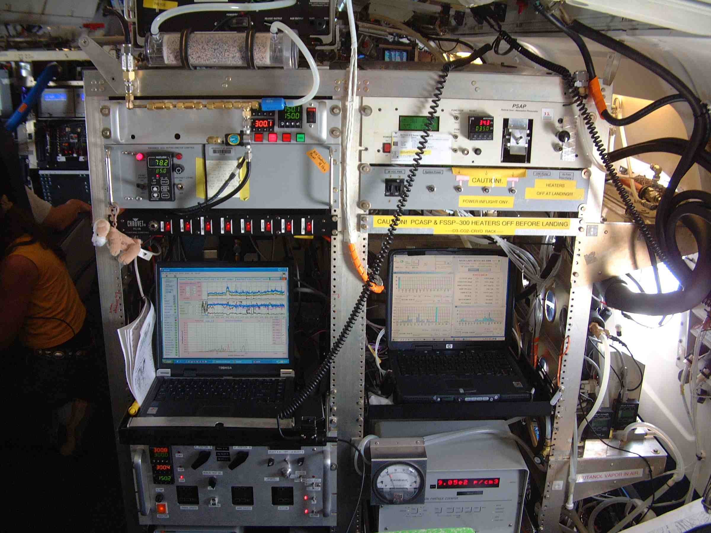
The Harvard QCLS (DUAL and CO2) instrument package contains 2 separate optical assemblies and calibration systems, and a common data system and power supply. The two systems are mounted in a single standard HIAPER rack, and are described separately below:

The Harvard QCL DUAL instrument simultaneously measures CO, CH4, and N2O concentrations in situ using two thermoelectrically cooled pulsed-quantum cascade lasers (QCL) light sources, a multiple pass absorption cell, and two liquid nitrogen-cooled solid-state detectors. These components are mounted on a temperature-stabilized, vibrationally isolated optical bench with heated cover. The sample air is preconditioned using a Nafion drier (to remove water vapor), and is reduced in pressure to 60 mbar using a Teflon diaphragm pump. The trace gas mixing ratios of air flowing through the multiple pass absorption cell are determined by measuring absorption from their infrared transition lines at 4.59 microns for CO and 7.87 microns for CH4 and N2O using molecular line parameters from the HITRAN data base. In-flight calibrations are performed by replacing the air sample with reference gas every 10 minutes, with a low-span and a high-span gas every 20 minutes. A prototype of this instrument was flown on the NOAA P3 in the summer of 2004.

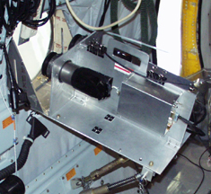
The Harvard QCL CO2 instrument measures CO2 concentrations in situ using a thermoelectrically cooled pulsed-quantum cascade laser (QCL) light source, gas cells, and liquid nitrogen cooled solid-state detectors. These components are stabilized along the detection axis, vibrationally isolated, and housed in a temperature-controlled pressure vessel. Sample air enters a rear-facing inlet, is preconditioned using a Nafion drier (to remove water vapor), then is reduced in pressure to 60 mbar using a Teflon diaphragm pump. A second water trap, using dry ice, reduces the sample air dewpoint to less than –70C prior to detection. The CO2 mixing ratio of air flowing through the sample gas cell is determined by measuring absorption from a single infrared transition line at 4.32 microns relative to a reference gas of known concentration. In-flight calibrations are performed by replacing the air sample with reference gas every 10 minutes, and with a low-span and a high-span gas every 20 minutes.

Instrument Type: 
Measurements: 
Aircraft: 
NCAR G-V, NOAA P-3, DC-8 - AFRC
Point(s) of Contact: 

Rosemount Icing Detector

The RICE is a magnetostrictive oscillation probe with a sensing cylinder 6.35 mm in diameter and 2.54 cm in length. Ice buildup on the sensing cylinder causes the frequency of oscillation to change, which can be related to the rate of ice accretion and hence the cloud liquid water content (LWC). When approximately 0.5 mm of ice has accumulated, a heater melts the ice, which is shed into the air stream. The heater cycle is approximately 5 s, and the cylinder normally requires an additional 5–10 s to cool down to a temperature where it can begin accreting ice again.

Point(s) of Contact: 

UNH Mercury

The UNHMERC instrument provides detailed information on atmospheric mercury. Measurements of total gaseous mercury (TGM) and gaseous elemental mercury (Hg°) are performed simultaneously with one minute time resolution using a custom four-channel atomic fluorescence spectrometer. The relative amount of reactive gaseous mercury (RGM = HgCl2 + HgBr2+ HgOBr + …) will be assessed through careful examination of the difference between TGM and Hg°. TGM is defined as the sum Hg° + RGM. Targeted aerosol sampling will also be conducted for particulate-phase mercury (HgP).

Measurements: 
Aircraft: 
Point(s) of Contact: 

Pages

Subscribe to RSS - DC-8 - AFRC